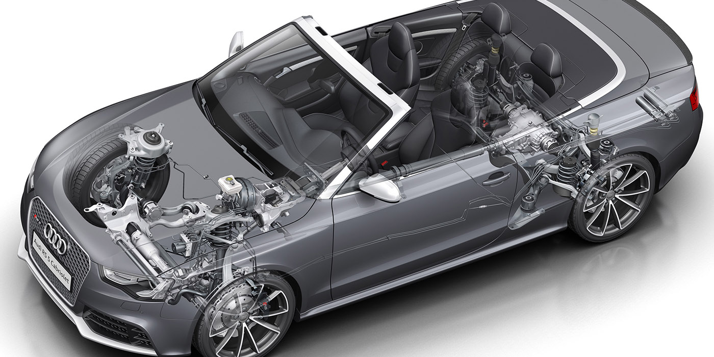
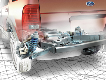
The 4-door Explorer and companion Mercury Mountaineer were redesigned entirely in 2002, losing all design similarity with the Ranger. The suspension on this Explorer has more in common with a car than a truck.
Beginning with the 2002 model year, Ford installed a fully independent rear
 suspension in the Explorer and Mercury Mountaineer (but not in the 2-door Explorer Sport). This replaced the non-independent (“live-axle”) rear suspension used in previous model year Explorers.
AdvanceTrac with Roll Stability Control were standard for 2005, but an option from 2002 to 2004.
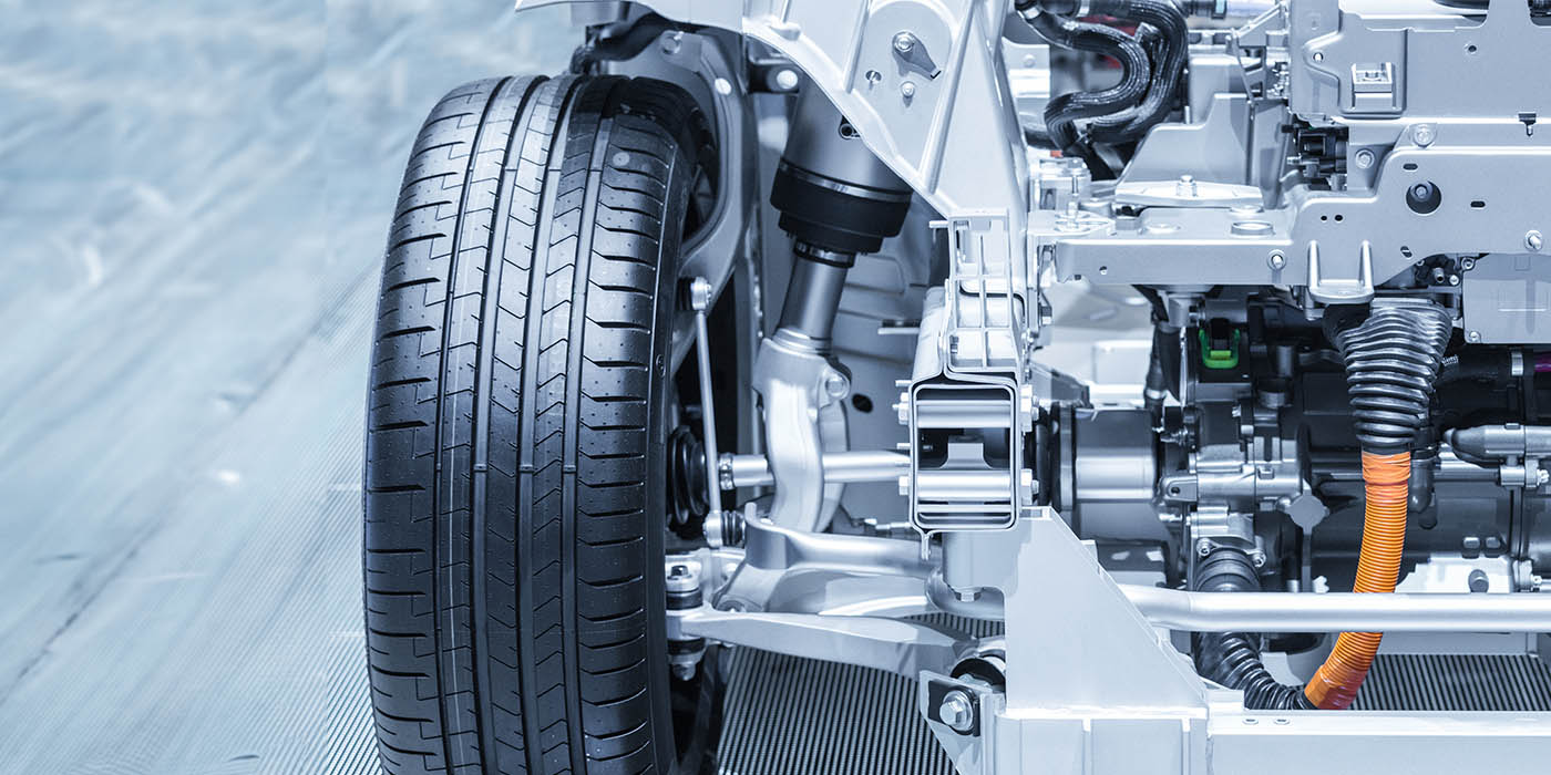
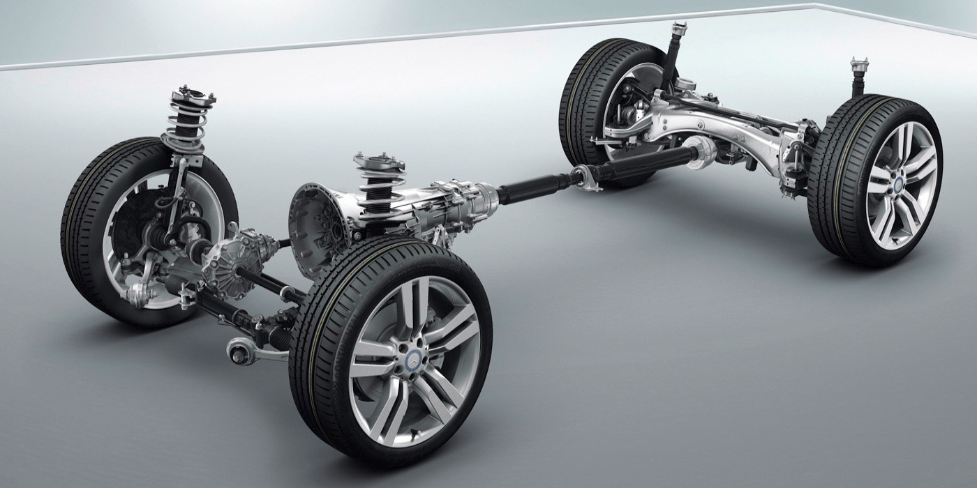
Front Suspension
The front suspension uses a SLA arrangement with stamped steel control arms. The knuckles are cast aluminum. Do not use an impact to tighten the ball joint stubs to the knuckle. If you do this, you could end up buying the customer a new knuckle.

The ball joints are pressed into the control arms. When installing a replacement ball joint, you may notice the new ball joint may not fit tight in the opening of the lower control arm.
The lower ball joint receptacle has been known to experience wear, especially when the ball joint has been replaced several times. If a traditional ball joint is installed in this situation, it will move and shift during operation, which can quickly wear out and damage the control arm.
Aftermarket chassis suppliers offer “oversized” ball joints for the Explorer to solve this problem. If you use one of these joints, make sure to ream the opening to the correct size for the new joint.
Another option is to install a new control arm if the bushings have too much play or the opening for the ball joints is damaged beyond repair.
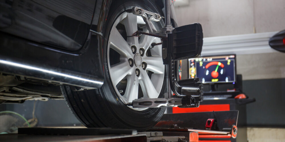
Front caster and camber is adjustable by replacing the stock alignment washers on the upper control arms. Caster and camber can be adjusted by turning the cam nuts to obtain the proper readings. These cam kits give you ±.75 degrees of camber and ±1.25 degrees of caster.
Rear Suspension
The rear suspension on the third-generation Explorer is a product of what they learned on the pervious generation. The fully independent rear uses two control arms and a toe-link.
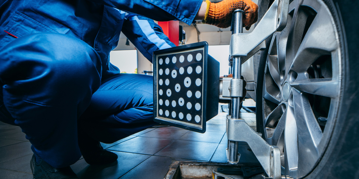
±.50 of camber adjustment can be made by replacing the stock alignment washer on the rear lower control arm and installing the plate and cam nut. This camber adjuster lets you easily adjust camber. Camber can then be adjusted by turning the cam nut until the desired readings are obtained. Toe can be adjusted with the toe link.
The ball joint on the upper control arm should have zero play and should be tested while the suspension is loaded. If the ball joint fails, the entire control arm should be replaced.
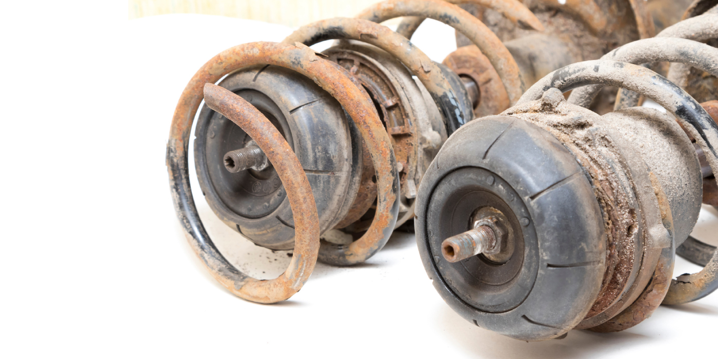
One problem with this generation of the Explorer is the rear springs. Many owners have reported the rear springs break. This usually occurs are the vehicle has exceeded 70,000 miles.
The symptoms of rear spring failure will be:
• Incorrect ride height
• Excessive front positive camber
• Clunking noise from the rear
Many ride control manufacturers offer loaded struts for the Explorer. The loaded strut is an assembled strut with a new spring and upper mount.
Another area for inspection is the rear-wheel hubs. Some units have failed with as little as 30,000 miles on the odometer.
TPMS
TPMS was an option on the Explorer. Ford systems use the unique ID numbers of the sensors that have to be registered along with their position on the car with the tire pressure monitor ECU.
This process requires the activation of the TPMS sensor using a low frequency radio signal tool or magnet to excite the sensor so UHF data is transmitted. The transmitted data includes the TPMS ID, the pressure and temperature. If a TPM sensor or its position on the car is changed without reregistering the IDs, the TPMS warning light will turn on and stay on until the IDs are reregistered. The sensors are mounted behind the valve stem.
1. Turn the ignition switch to the OFF position.
2. Turn the ignition switch to the RUN position three times, ending in the RUN position. Do not wait more than two minutes between each key cycle.
3. Press and hold the brake pedal.
4. Turn the ignition switch to the OFF position.
5. Turn the ignition switch to the RUN position three times, ending in the RUN position. Do not wait more than two minutes between each key cycle.
6. When the message center displays “TRAIN LEFT FRONT TIRE,” place the magnet on the valve stem of the LF tire pressure sensor. The horn will sound briefly to indicate that the tire pressure sensor has been recognized by the TPMS module.
7. Within two minutes after the horn sounds, place the magnet on the valve stem of the RF tire pressure sensor.
NOTE: If the TPMS module does not recognize any one of the five tire pressure sensors during the tire training procedure, the horn will sound twice and the message center will display “TIRE TRAINING MODE INCOMPLETE” and the procedure must be repeated.
8. Repeat Step 7 for the RR, LR and spare tire.
When the tire training procedure is complete, the horn will sound twice and the message center will display “TIRE TRAINING MODE COMPLETE.”