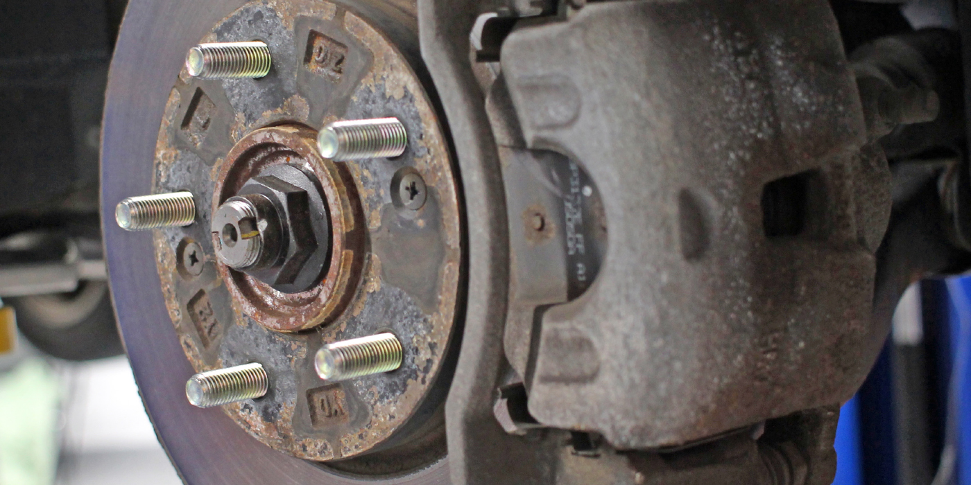
The fourth generation Dodge Ram is probably one of the most trouble-free brake systems you’ll see. There are light- and heavy-duty brake packages. The light-duty package for the 1500 uses floating dual piston calipers in the front and single piston floating calipers in the rear. The heavy-duty package for the 2500 and 3500 uses floating dual piston calipers in the front and dual piston floating calipers in the rear.
The light-duty brake package uses spring clips on the ends of the brake pad that reduce brake drag and noise. These clips should always be replaced with the brake pads. The heavy-duty package uses abutment clips that snap over the slides on the bracket. Servicing the pads and rotors is simple, typically with few surprises.
The torque specifications for the light-duty package are 130 ft/lbs for the front caliper brackets and 120 ft/lbs for the rear caliper brackets. The heavy-duty front brake caliper bracket has a torque specification of 275 ft/lbs. The rear caliper bracket for the heavy-duty caliper has a torque specification of 163 ft/lbs for the upper bolt and 190 ft/lbs for the lower bolt. Both versions have a torque specification of 32 ft/lbs for the guide pins.
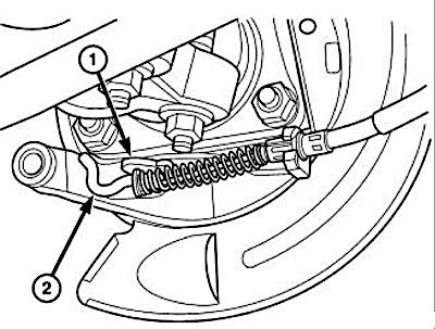
Parking Brake
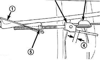
Parking brake adjustment is controlled by a cable tensioner mechanism.
- Back off the cable tensioner adjusting nut (5) to create slack in the cables.
- Remove the rear wheel/tire assemblies. Then remove the brake rotors.
- Verify the brakes are in good condition and operating properly.
- Verify the park brake cables operate freely and are not binding or seized.
- Check the rear brake shoe adjustment with standard brake gauge.
- Install the rotors and verify that the rotors rotate freely without drag.
- Install the wheel.
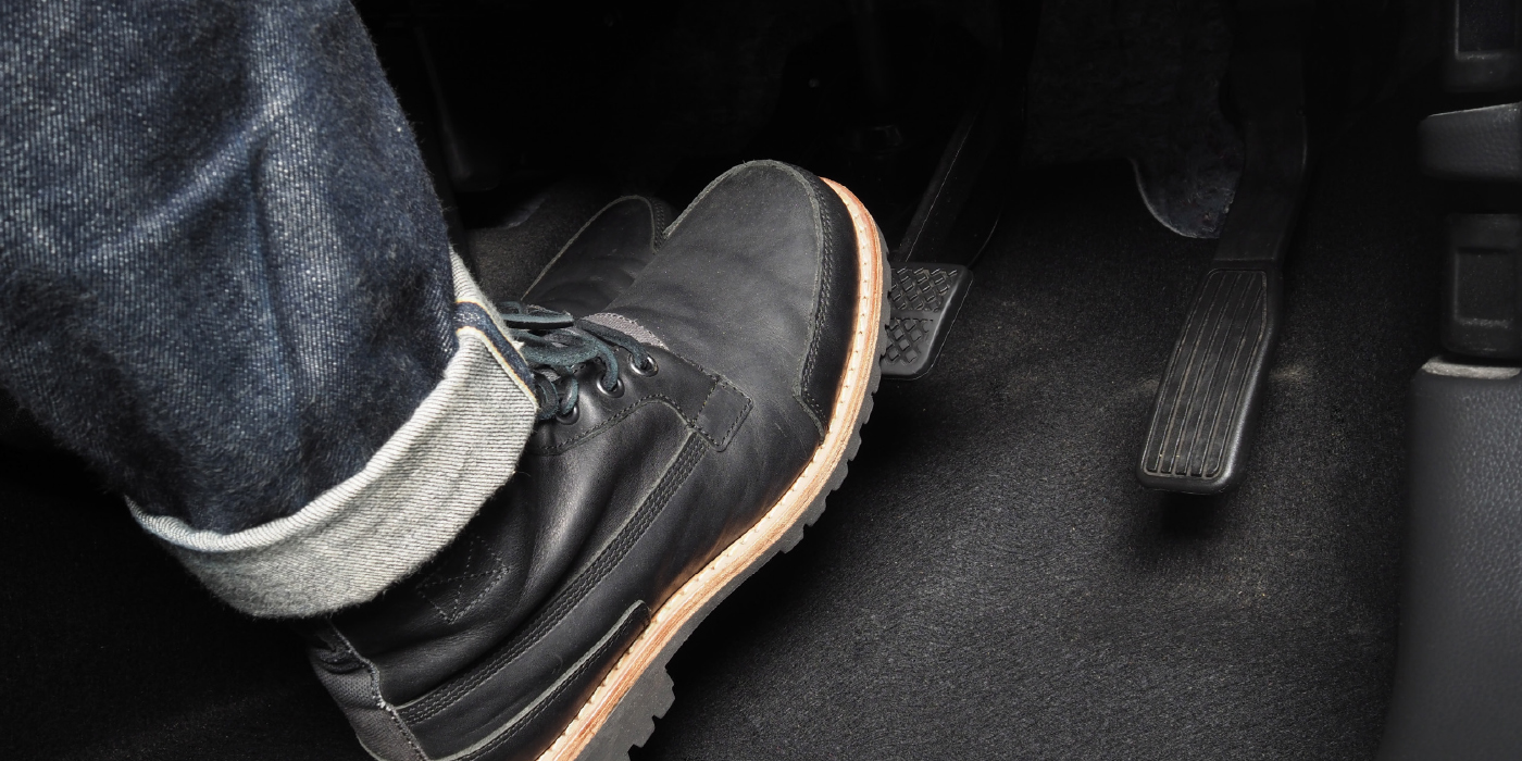
- Lower the vehicle enough for access to the park brake foot pedal. Then fully apply the park brakes.
Trailer Brakes
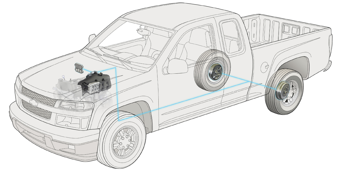
Most models come with an Integrated Trailer Brake Module (ITBM). This unit is designed to not only operate the lights, but also to actuate electric trailer brakes. It uses an accelerometer to control the trailer brakes. The ITBM is located in the instrument panel to the left of the steering column above the park brake release handle. Near the center of the ITBM is a numerical LED and trailer icon which illuminates for three seconds when the ignition switch is placed in the RUN position. There is also an adjustment switch and a trailer manual sliding brake lever/switch on the face of the ITBM.
The ITBM is powered with an ignition ON voltage source and has a single ground connection. The ITBM communicates on the CAN bus for vehicle speed signal, Electronic Stability Control (ESC) active signal and VIN information. There is also a hardwired brake switch input into the ITBM.
The ITBM uses this information along with an internal accelerometer to determine how much braking to apply to the trailer brakes. The output is a Pulse Width Modulated (PWM) circuit for control of the trailer braking intensity during stops. The ratio between vehicle braking and trailer braking is adjusted by the user with the plus/minus (±) switch on the face of the module.
In addition to automatic trailer braking, the user can manually apply the trailer brakes prior to, or without, using the vehicle brakes by sliding the ITBM manual sliding brake lever/switch to the right at any time. In this circumstance, the accelerometer and other trailer braking inputs are ignored, and trailer braking intensity is controlled by the user.
To pull codes:
- Disconnect all jumper wires and reconnect all previously disconnected components and connectors.
- Make sure all accessories are turned off.
- With the scan tool, record and erase all DTC(s) from the ITBM.
- Start the engine and allow it to idle for two minutes while operating all functions of the system that caused the original problem.
- Perform the ITBM VERIFICATION TEST.
- Turn the ignition off, wait five seconds, then turn the ignition on. Using the scan tool, read DTC(s) from the ITBM.