Since the 2000 model year, GM has offered electronically adjustable suspension as an option on Chevy, Cadillac and GMC full-size trucks. The system actuates the valving in the shocks to control suspension position and body attitude.
 The electronic suspension control (ESC) system independently controls each of the four shock absorbers in order to control the vehicle ride characteristics, capable of making changes within milliseconds. The ESC system has its own module that is independent of the air ride system, but it does communicate and share suspension position and other information on a serial data bus.
The system measures the position of the suspension using sensors mounted to the chassis. The sensors are very sensitive and have three-wire connections.
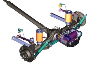 The system features links that attach to the front upper control arms or rear trailing arm. These links can be damaged by road debris, or the nylon ball and stud can wear out — all seen with an easy visual inspection. If a sensor is replaced or repaired, you will have to use a scan tool to recalibrate the height.
The shock absorbers contain the actuators that move the valves in the shocks. These can’t be serviced; they are connected to the vehicle using a two-wire connection. The actuation or position is one to 100 percent.
The ESC controls the damping mode selection according to inputs that include vehicle speed, pitch, steering angle and body-to-wheel displacement. The ESC module evaluates these inputs, shared along a CAN bus, in order to separately control the shock absorbers, which provides an enhanced ride and comfort level over the widest possible range of operating conditions.
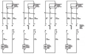
The Electronic Shock Control (ESC) Module is connected to the suspension position sensors and shock absorber actuators. It is also connected to a high-speed bus so it can use data from the speed, yaw and steering angle sensors.
ESC Module
The ESC module provides electronic control logic and output drive for each shock absorber. The ESC module makes decisions based on the road and driving condition information gathered from various inputs.
The ESC position sensors are mounted at each corner of the vehicle between the control arm and the body/frame. They provide the ESC module with the body-to-wheel displacement input. The ESC module uses this and other inputs in order to control the stiffness of the shock absorber. If any body or wheel motion is detected, the ESC module will determine how soft or firm each shock absorber should be to provide the best ride.
ESC Diagnostics
The ESC system does not have a malfunction indicator lamp, but instead uses the instrument panel cluster for the display functions. When the ESC system detects a malfunction that sets a DTC, the ESC system sends a message on the serial data line directly or through the powertrain control module (PCM) to the IPC, which will display one of the following messages:
• SHOCKS INOPERATIVE
• SERVICE SUSPENSION SYSTEM or SERVICE RIDE CONTROL
• SPEED LIMITED
The SHOCKS INOPERATIVE message will only be displayed if the ESC system detects a malfunction that sets a DTC and causes the ESC system to disable all four shock absorbers.
The SERVICE SUSPENSION SYSTEM or SERVICE RIDE CONTROL messages will only be displayed if the ESC system detects any malfunction that sets a DTC.
 The SPEED LIMITED message will only be displayed if the ESC system detects a malfunction that sets a DTC and causes the ESC system to disable all four shock absorbers. The ESC system will send a message on the serial data line to the PCM indicating that all four shock absorbers were disabled.
The ESC module has the ability to store DTCs as current or history codes. Most ESC system malfunctions will display a message in the IPC and set a DTC. The message will remain on until the RESET button is pressed on the driver information center (DIC). As long as the DTC is current, the message will be displayed after every ignition cycle and the RESET button must be pressed to bypass the message.
If the ESC detects a malfunction, the ESC system defaults with a fail-soft action, which refers to any specific action the ESC system takes in order to compensate for a detected malfunction. A typical ESC fail-soft action is if the ESC system detects a malfunction with a shock absorber.
The ESC system uses an ignition cycling diagnostic approach in order to reduce the occurrence of false or intermittent DTCs that do not affect the functionality of the ESC system. This allows for the fail-soft actions to be taken whenever a malfunction condition is current, but requires the malfunction to remain current for a certain number of ignition cycles before the corresponding malfunction code and message will be stored or displayed.
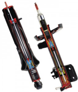
ESC Shock Absorbers
The ESC shock absorbers provide variable damping to resist suspension movement and have the capability to provide multiple modes or values of damping forces, in both compression and rebound direction. The damping forces are modified utilizing electrical actuators located internally within the shock absorbers.