 The Nivomat Shock Absorber is a self-leveling monotube shock absorber developed by Sachs. Nivomat is a contraction of two French words, niveau and automatique. When translated to English, it would be level automatic or automatic level.
Nivomat shocks are used by Chrysler, Ford, General Motors, Jaguar, Kia, Mitsubishi, Saab, Volvo and other OEMs. The system is also available on the GM Suburban and Tahoe as part of ZW7 Premium Smooth Ride Suspension. Replacement units are available from Monroe, ZF Sachs and OES suppliers.
The system makes use of the mechanical energy which is generated during the first meters of driving from the relative movement between the axle and vehicle body.
An unlevel vehicle can create many problems. Extra weight on the rear axle shifts the center of gravity, which has a major impact on the ride characteristics. In critical situations, the vehicle can be very difficult to control. Under these conditions a “floaty” ride characteristic can not be considered as comfort anymore.
Other effects are increasing expenses: The tires wear unevenly and faster. Bad aerodynamics causes a higher fuel consumption. Greater strain is also placed on the axle as a whole.
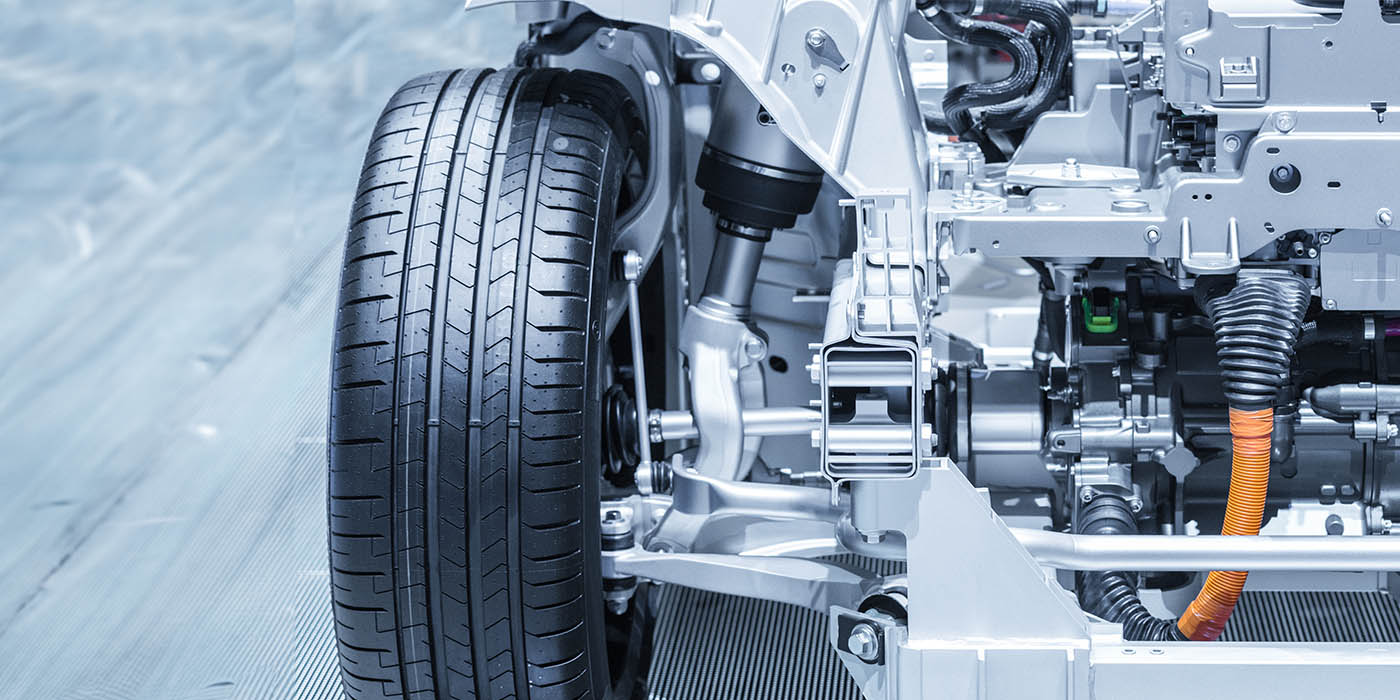
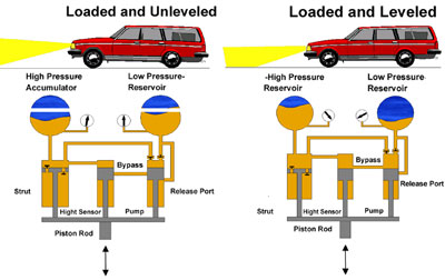
In place of conventional shock absorbers, this unique system is installed on the rear axle. While providing additional roll stability without requiring any additional electronics, the Nivomat adjusts the vehicle to the optimum ride height for every load condition, thus ensuring a safe and comfortable ride.
The Nivomat system does more than just level the vehicle under load. As the load increases, the pressure inside the shock increases as oil is displaced from the reservoir to the inside of the unit, compressing the gas volume. This creates a progressive increase in spring rate and damping with little or no change to ride frequency.
 The Nivomat is like an ordinary monotube shock absorber with a hydraulic piston, tube and accumulator. There are two different configurations of the shock. The first looks like a conventional twin tube air shock with a dust cover. What appears as a dust cover houses the high pressure accumulator and low pressure oil reservoir.
The second configuration has its high pressure accumulator at the top of the shock. This reduces the overall diameter of the shock. This allows the shock to be installed in a more confining space, such as an independent rear wheel drive suspension and can be mounted in a shaft up or down configuration as designed by the manufacturer. The normal application for this shock absorber is for the rear suspension of a passenger car or SUV.
What gives the shock its leveling capability is a pump mechanism and oil reservoir that can increase the accumulator pressure, which increases the shocks lifting capability. It is used in combination with springs matched to the load capacity of the shock to reduce suspension travel while utilizing more of the piston and shaft travel of the shock.
This maintains the ride quality whether the vehicle is operated with a driver only or to compensate for passengers and luggage. The big advantage to the Nivomat is the shock absorber requires no plumbing, compressor and height sensing device to level the vehicle. The normal movement of the suspension over a regular road surface provides enough pumping action to level the vehicle.
Leveling Components:
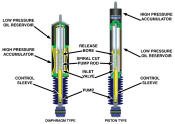 The accumulator can be a diaphragm or piston. The normal pressure contained the accumulator ranges from 20 bar (290 psi) to 50 bar (725 psi). The pump can increase the accumulator pressure from 90 bar (1305 psi to 130 bar (1885 psi). Under driving conditions, pressure can reach 350 bar (4,424 psi).
The control sleeve is fixed in the shaft and controls oil flow through the spiral cut and release bore in the pump rod. The inlet valve is a one way check valve located at the end of the spiral cut in the hollow pump rod.
The low pressure oil reservoir contains the oil used to charge the pump mechanism. The pump is located at the end of the control sleeve and uses a pump cup, pump and balance spring.
Leveling Operation:
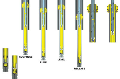
The Nivomat shaft and piston provide the same damping as a normal monotube shock. The difference is that the shaft is hollow and contains the pump mechanism. The pump is operated by the displacement of oil caused by the movement of the shaft in and out of the shock. When the piston shaft moves out of the shock, oil is drawn from the low pressure oil reservoir through the hollow pump rod and inlet valve into the pump chamber.
Since Nivomat is mechanical, the vehicle needs to be moving before the pump starts to work and it takes about a mile to a mile-and-a-half of travel before the vehicle reaches its optimal level point.
The pump is made up of a pump cup and balance spring. When the piston shaft moves into the shock, the oil is compressed collapsing the pump spring and expanding the balance spring to fill the pump cup. When the shaft moves out of the shock, the control sleeve opens the spiral cut in the pump rod, and the oil is forced into the main chamber of the shock. The pump and balance spring return the pump cup to its level position. This increases the pressure in the accumulator creating more lift to return the piston and shaft to the level position. In the level position, the control sleeve closes the spiral cut and the shock operates normally until the next inlet and pump action.
The release bore is used to return the shock to the level position when the load is removed from the vehicle. When the shaft and control sleeve is extended out of the shock past the release bore, the oil that was pumped to increase the accumulator pressure and lift is returned to the low pressure reservoir.
Installation:
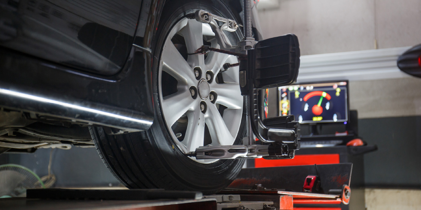
When replacing a load leveling shock absorber, it is necessary to inspect both mounting points for damage and stress cracks. All mounting hardware should also be replaced. All fasteners should be tightened to their proper torque specifications.
The diameter of a conventional shock absorber is 54 mm (2-1/8-in). The diameter of a Nivomat shock can range from 60 mm (2-5/8 in) to 72 mm (2-7/8 in). Make sure the shock is properly mounted to provide adequate clearance. It is recommended to test the operation of the shocks by loading and driving the vehicle.
 Disposal
Take the following steps, making sure to comply with local safety and environmental protection regulations to recover and dispose of the oil before scrapping the shock.
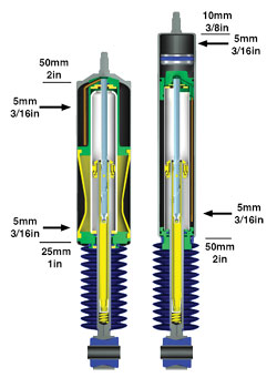
Diaphragm Type (Except Mercedes Benz M Class)
1. Clamp the shock in a horizontal position using a vice with the shaft fully extended.
2. Center punch a mark 50 mm (2 in) from the top of the tube.
3. Drill a 5 mm (3/16 in) hole to exhaust the gas and oil from the low pressure reservoir.
4. Center punch a mark 25 mm (1 in) from the bottom of the shock’s tube.
5. Drill a 5mm (3/16 in) hole to exhaust the gas from the high pressure accumulator.
6. Remove the remaining oil in the shock by pumping the shaft in and out of the tube.
7. The shock can now be scraped.
Piston Type (Mercedes Benz M Class)
1. Clamp the shock in a horizontal position using a vice with the shaft fully extended.
2. Center punch a mark 50 mm (2 in) from the bottom of the tube.
3. Drill a 5 mm (3/16 in) hole to exhaust the gas and oil from the low pressure reservoir.
4. Center punch a mark 10mm (3/8in) from the top of the tube.
5. Drill a 5 mm (3/16 in) hole to exhaust the gas from the high pressure accumulator.
6. Remove the remaining oil by pumping the shaft in and out of the tube.
7. The shock can now be scraped.