When the topic of variable valve timing (VVT) comes up, few realize that the concept of increasing low- and high-speed engine torque by automatically advancing and retarding valve timing isn’t a recent development. For example, I recently discovered an old variable camshaft timing gear that I bought during the 1960s featuring a torsion spring device that retards valve timing in response to the increased rotating torque needed to turn the camshaft at higher engine speeds.
In theory, I could enjoy the advantages of low-speed torque and high-speed horsepower. In practice, however, it didn’t seem to work due to its reliance on rotating torque.
Nowadays, a historical discussion of the various engineering approaches to variable valve timing could fill an encyclopedia. But computerized engine management systems have made variable valve timing a practical reality for most vehicles.
Coupled with tuned intake and exhaust systems, variable valve timing can dramatically increase low- and high-speed engine torque, increase fuel economy and reduce exhaust emissions. 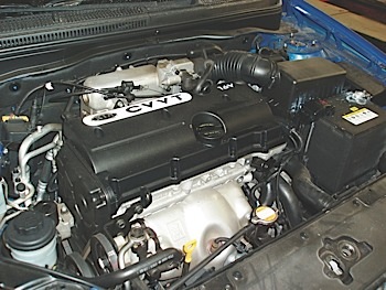 On the other hand, variable valve timing has brought with it some specific issues concerning engine lubrication and diagnostics.
To keep this text simple and to the point, I’ll leave the more unique VVT designs to the pages of history and electronic valve timing to the pages of the future. In the meantime, let’s look at the basics of how VVT affects engine performance, how it might fail and then follow up with a few tips on how to troubleshoot suspect VVT systems. See Photo 1.
TERMINOLOGY
The variable “valve” timing that most of us see in our shops is actually variable “camshaft” timing that improves low- and high-speed torque by advancing or retarding the camshaft timing on single overhead camshaft (SOHC) engine applications.
In contrast, some double-overhead camshaft (DOHC) applications perform those same functions by separately advancing or retarding the intake and exhaust camshafts.
Fully variable valve timing can be achieved only by using computer-operated solenoids to precisely control the intake and exhaust valve opening and closing events. Although the various combinations of valve timing events are theoretically infinite on an electronically controlled system, its applications are limited due to issues of cost and, in some cases, reliability.
OPERATING PRINCIPLES
Effective valve timing is very dependent upon the velocities of the intake air flowing through the engine’s intake ports and the exhaust gases flowing out of the engine’s exhaust ports. On most naturally aspirated engines, the intake valve doesn’t close until the piston begins moving upward on compression stroke. When intake air is moving slowly at lower engine speeds, the intake valve should close early to prevent the piston from pushing the intake air back into the intake port and manifold.
But when intake air velocities increase with engine speed, the intake valve should close later to help pack more air into the cylinder. In theory, most VVT designs begin to change intake valve timing when intake air velocities begin to dramatically increase at 2,500 to 3,500 rpm. Of course, the PCM’s actual operating strategy depends largely upon the engine design and the speed limitations of the engine.
While exhaust valve timing isn’t as critical to engine performance as intake valve timing, it theoretically can be advanced on DOHC applications to increase valve timing overlap at higher engine speeds and retarded to reduce valve overlap at lower engine speeds.
Valve timing overlap is desirable at higher engine speeds. Simultaneously holding the intake and exhaust valves open as the engine goes from exhaust to intake stroke allows the engine to make use of the slight negative pressure created by exhaust gases exiting the exhaust port to help draw the intake charge into the cylinder.
But at lower engine speeds and gas velocities, high valve overlap produces a loping idle due to exhaust gases pushing back into the intake manifold, plus it reduces engine running compression. Keep in mind also that changing the exhaust valve timing can create an “EGR” effect that helps reduce Nitrogen Oxide (NO) emissions in some applications.
CAM LOBE DESIGN
In passing, it’s helpful to understand the basics of camshaft lobe design. To prevent excessive stress on the valvetrain, a cam lobe must be designed to gradually accelerate the mass of the lifter, push rod, rocker arm and valve. Overhead camshaft designs reduce valvetrain stress by replacing these components with a simple cam follower.
 Unfortunately for mechanical camshafts, variations in valve lash will cause slight changes in valve timing. Since hydraulically adjusted camshafts don’t require a lash clearance, valve timing remains very consistent.
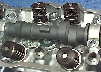
In either case, the cam lobe must be designed to gradually decelerate the valvetrain to prevent valves from bouncing off the valve seats at peak engine speeds. While camshaft lobes can be ground to increase air flow by increasing valve lift, the increased valve lift increases stress on the valvetrain as well as the potential for piston-to-valve interference. See Photo 2.
VVT HARDWARE
Variable camshaft timing on early single-overhead camshaft (SOHC) engines was achieved by using a camshaft “phaser” consisting of a spring-loaded hydraulic piston forcing a beveled drive gear against a similar beveled drive gear mounted on the camshaft.
Precise camshaft timing can be achieved by using the Powertrain Control Module (PCM) to apply oil pressure to the piston by pulsing an oil control valve. Since the piston incorporates an orifice to bleed away oil pressure, cam timing can be changed by increasing the pulse width applied to the oil control valve.
If the electronics fail, a phaser return spring will push the piston to its default timing position. 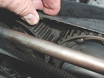 The PCM will also monitor camshaft position by comparing the relative positions of the camshaft position sensor (CMP) and the crankshaft position sensor (CKP). If those positions don’t correspond with the programmed data, the PCM should set a P0010-series or P0340-series trouble code.
Some VVT designs also incorporate a separate valve timing sensor (VTS) to provide a more precise valve timing feedback to the PCM. While most modern VVT designs use the more compact vane-type phasers to adjust valve timing, they continue to use the same basic arrangement of sensors and oil pressure control mechanisms to allow computer control. See Photo 3.
DIAGNOSTIC TIPS
As you might have already guessed, VVT diagnostics is very application-specific because it not only depends upon whether the engine is an in-line or V-type block, or a SOHC or DOHC configuration, but also upon the configuration of the phaser and system electronics. In addition, there are literally dozens of “global” P0010- and P0340-series trouble codes, not to mention manufacturer-specific P1000-series codes that can be stored due to a valve-timing problem. But, by applying basic operating principles, it’s possible to diagnose most VVT failures, regardless of configuration.
It’s obvious that most VVT failures will result in a loss of low- or high-speed engine torque and affect intake manifold vacuum. When the camshaft is not responding to the positions commanded by the PCM, the PCM should store a camshaft-related timing P0340-series error code. On V-block engines, a camshaft timing error on one bank might also result in P0300-series misfire codes for all cylinders on that bank.
In addition, remember that valve timing and valve overlap affect cylinder compression. With a single-bank failure on a V-block engine, the bank-to-bank cranking compression should differ, as should the bank-to-bank fuel trim numbers. Also, keep in mind that with the re-introduction of steel timing chains, a single loose chain or a worn tensioner or chain guide on one bank can retard cam timing and perhaps affect cold starting and driveability performance.
Engine oil viscosity as well as oil filter flow capacity can definitely affect the ability of the cam phaser to control valve timing, as can the service life ratings of the oil.
In many cases, a non-OE approved oil, coupled with a low-capacity oil filter, can cause sludging or varnishing, which causes cam phasers to stick in advanced or retarded positions. This may also cause the oil passages in the cylinder head, oil control valve and phasers to clog with sludge or become contaminated with metal chips. Even when using OE or OE-approved oils, keep in mind that engine oil must be changed at recommended intervals.
Last but not least, many advanced diagnostic technicians routinely collect labscope samples of known-good CMP and CKP sensor waveforms for future comparison with those produced by a similar model afflicted with a suspected valve timing problem. But that’s a story unto itself.
For the meantime, it’s a good idea to check each VVT vehicle for scan tool-based cam timing data and to stay on top of current VVT issues by monitoring on-line information sources and the pages of ImportCar magazine.