It’s 1956 and the 20-inch-diameter steering wheel on a Chevrolet Bel Air or Ford Fairlane provided the leverage to steer the wheels. But, it was especially difficult to turn the steering wheel when the vehicle was stopped. Turning the wheel required a certain amount of upper body strength that was given by God to truck drivers of the day.
When the Saginaw recirculating ball steering gear was introduced on the 1940 Cadillac, it provided a little more mechanical advantage, but it was still hard to turn the wheel when the vehicle was stopped. If the car makers of the era were going to sell more vehicles, especially to the new suburbanite homemakers, they were going to have to be easier to steer and shift. The premium vehicles, Cadillac, Lincoln and Chrysler, were adding power steering to their optional and standard equipment lists, but they were still the most expensive cars in the dealers’ showrooms.
 By the start of the 1960s, power steering was an option or standard on all American-built vehicles. In the late 1960s and into the early 1970s, the big steering wheel still graced steering columns. The large diameter of the steering wheel made the power steering very sensitive to input at higher speeds. To reduce the input sensitivity, the diameter of the steering wheel was made smaller. Most vehicles today have a 14- or 15-inch steering wheel.
The age of power steering
There are two types of conventional power steering systems. The first type uses a hydraulic cylinder attached to the drag link and the chassis. A control valve is attached to the end of the drag link replacing the tie rod end and the valve actuator is connected by a tapered shaft to the pitman arm.
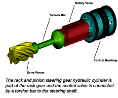
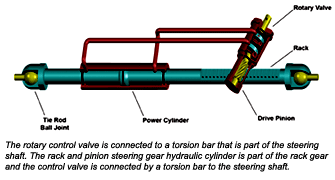
The second type uses a hydraulic cylinder that is an integral part of the steering gear and is connected to the recirculating ball nut located on the steering shaft. The rotary control valve is connected to a torsion bar that is part of the steering shaft. The rack and pinion steering gear hydraulic cylinder is part of the rack gear and the control valve is connected by a torsion bar to the steering shaft. In all these types of power steering, the pump delivers fluid to the control valve. The control valve opens a pressurized flow to and from the hydraulic cylinder.
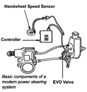 The control valve responds directly to input from the pitman arm or steering shaft. The actuation of the control valve is based on input geared to slower vehicle speeds where assist is needed the most. This configuration makes the steering more sensitive at higher speeds. In the 1980s, modifying the flow from the pump to the cylinder started to be used as a method to reduce high-speed sensitivity. This control system is called an Electronic Variable Orifice (EVO).
The EVO valve is mounted at the power steering pump outlet. The valve uses an electronic controller to produce magnetic field changes in the valve’s solenoid coil. The valve pin attached to the orifice valve extends into the solenoid coil. The magnetic field generated by the solenoid coil will pull the pin into the coil. This pulling action regulates the flow through the valve. The valve and controller can be used with rack and pinion and conventional systems.
An electronic controller changes the magnetic field in the solenoid coil by sending a Pulse Width Modulated (PWM) voltage to the coil. The controller adjusts steering effort based on vehicle speed input to the controller and steering wheel position. Vehicle speed input normally comes from the Engine Control Module (ECM).
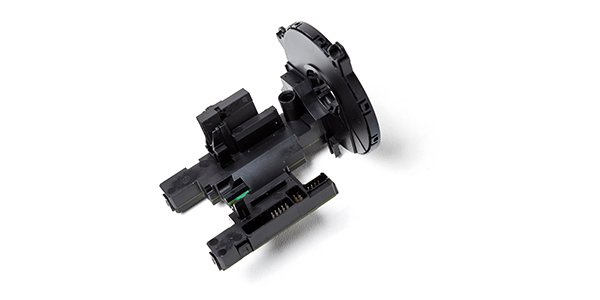
Steering wheel position comes from the Hand Wheel Speed Sensor (HWSS). It measures the speed at which the steering wheel is being turned and produces a variable analog voltage signal to the controller. The signal will vary from a high voltage to a low voltage and return to high voltage as the steering wheel is turned through 180 degrees of rotation. A combination of vehicle speed and rate at which the steering wheel is being turned will produce a PWM signal from the controller to the solenoid coil varying the amount of assist.
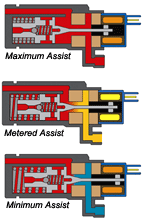 During parking maneuvers, when there is no vehicle speed input, the orifice control valve has no magnetic field and provides high pump flow for low steering effort. At highway speeds, the orifice control valve magnetic field is increased to reduce the flow in proportion to vehicle speed to achieve higher steering effort and reduce input sensitivity to the steering wheel. When the controller receives both a vehicle speed input and HWSS input. It will increase the magnetic field to decrease the pressure and flow to provide less assist and increase steering effort.
The HWSS has four voltage divider circuits and a “wiper” for the sensor wheel. The voltage dividers are constructed of a resistive material on a film powered by a 5-volt reference to make four 90-degree sensing elements. The wiper has a contact that rides on the resistive film and supplies the output signal to the controller. The signal ranges from 0.5 to 4.5 volts with a plus or minus 0.3 volts. For example: The sensor produces 0.2 to 4.8 volts when the steering wheel is rotated 90 degrees. Then the sensor produces 4.8 to 0.2 volts for the next 90 degrees of steering wheel rotation in the same direction. When the steering wheel has been rotated 360 degrees, the voltage will have gone 0.2 to 4.8, 4.8 to 0.2, 0.2 to 4.8 and 4.8 to 0.2 volts in a constant rising and falling voltage.
Failure Modes and Effects
What happens when the coil in the EVO valve fails? The power steering pump will deliver full pressure and volume to the hydraulic cylinder. Steering the vehicle will be more sensitive than when the valve was operating and will exist under all driving conditions.
What happens when the valve fails in the closed position? Steering the vehicle will require more effort as there will be little or no assist.
 What happens when a sensor fails? When a sensor or input fails, it will most probably produce an intermittent failure. An intermittent interruption to the vehicle speed input to the controller will produce an increase in power assist. This condition can be detected when the vehicle is moving, as the steering wheel is sensitive to small inputs. The controller is in parking mode with the pump delivering full steering assist.
An intermittent interruption of the HWSS with the vehicle moving will produce minimum power assist. This will be detected as a sudden increase in steering effort when the vehicle is turning a corner.
Diagnostics
Some vehicles will have Diagnostic Trouble Codes (DTC) for input and output failures. Listed are generic OBD II diagnostic trouble codes:
C0472 – Steering Handwheel Speed Sensor Signal V Low;
C0473 – Steering Handwheel Speed Sensor Signal V High;
C0495 – EVO Tracking Error;
C0498 – Steering Assist Control Actuator Feed Circuit Low;
C0499 – Steering Assist Control Solenoid Feed Circuit High;
C0503 – S teering Assist Control Solenoid Return Circuit Low; and
C0504 – Steering Assist Control Solenoid Return Circuit High.
This is where a scan tool can help in quickly diagnosing the problem. Another valuable tool is a digital multimeter that can measure pulse width. It can provide diagnostic and component test information. Some of the most important diagnostic and repair solutions can come from service information. There may be a technical service bulletin out there that describes the condition and repair for the vehicle. Take advantage of all your diagnostic options before starting the repair.

